
Author: Emanuel Perez
Written & Edited By: Steve Sumner (ncSteve)
The following is a brief description of how to install a Central Fuel Injection (CFI) system onto a 2.8 liter and what components are needed. Keep in mind that this conversion takes a bit of time and patience.
Components:
First you will need a complete 2.9 liter fuel injection engine harness and Power-train Control Module (PCM) from a Ford Ranger or Bronco II. Second, you will need a 3.8 liter fuel injection throttle body from any rear wheel drive Ford car with a 3.8 liter. The 3.8 liter used in a Ford Taurus is the Wrong fuel injection system(it is the multi-port type), it must be a TBI (Throttle-body fuel injection) unit (with only two injectors) removed from a Mustang, LTD II, Thunderbird, or Cougar. This system has a throttle body similar to a carburetor.
You will want to start out by removing the original Ranger carburetor and computer wiring harness, original PCM, and all vacuum lines and solenoids, leaving the engine compartment free of all original computer equipment. The sensors and vacuum solenoids from the 2.9 need to be used, as the 2.8 liter units will not plug into the harness. The exception I found is the 6-wire plug for the TFI module on the distributor, which will plug into the 2.8 distributor.
The sensors and components needed are: Coolant temp sensor (not for the gauge), Manifold absolute pressure sensor, Heated O2 sensor, Air charge temperature sensor, idle speed control air bypass valve, EVR solenoid, and EGR valve. The throttle position sensor, idle speed control motor, and injector assembly will already be mounted on the 3.8L TBI unit. You will need to remove the idle speed control motor from the TBI unit. You will also need the connectors (from the harness) that plug into the throttle position sensor and the injector array.
The other parts needed are as follows:
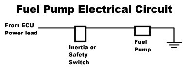
Fuel pump relay and inertia switch.
Fuel pump (I used an after market Holley)
High pressure fuel filter
Fuel pressure regulator (optional)
P/N: 510-512-103 – Holley in-line Universal High Pressure Electric Fuel Pump
P/N: 510-512-500-1 – Holley Fuel Pressure Regulator
Note: When removing the PCM and wiring harness from the 2.9 liter engine be sure to LABEL EVERYTHING, you will save yourself a lot of trouble.
Details:
The computer, if operational, will work well on the 2.8 liter engine. When routing the wiring try to keep it as close to the original path as possible, though some lengthening and/or shortening will need to be done. The best method for this is to solder the wires and use shrink wrap around them.
As for the fuel pump, the mechanical fuel pump and fuel lines the entire way back to the tank need to be removed and replaced with a high pressure in tank setup. Make a block off plate for the hole left by the mechanical fuel pump, and be sure to remove the push rod from the engine.
One option is to get the steel lines from the 2.9 Ranger FI tank and ALL associated lines, wiring and pumps, these will need to be installed into your Bronco II or Ranger.
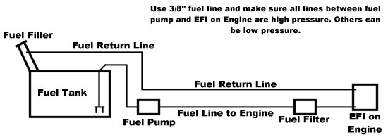
Another option for the fuel pump is to install an inline electric pump near the fuel tank. If this method is chosen, install a high pressure fuel filter after the pump, and run the return line back to the fuel tank filler neck. I installed the pump very close to the fuel tank and ran a high pressure fuel line up to the engine compartment. This fuel line is very expensive, so the shorter the better. I then installed a high pressure fuel filter from Summit Racing, and continued to the TBI. For the return line I ran a short rubber hose to the original steel line and then from the end of the original line near the tank I ran a rubber hose to an AN style bulkhead fitting into the filler neck of the fuel tank. For safety, you may also wish to incorporate an inertia switch into the electrical side of the system. The fuel pressure needs to be at 39 PSI, and should be kept in that neighborhood.
As far as wiring goes, you will need a diagram from the 2.9L and your Ranger. The electrical harness on the driver’s side of the vehicle will supply the required powers, and the grounds should just go to the frame or chassis. Be extremely careful when wiring the ECM, if you’re not sure about which wires go where, asked somebody. The ECM can be destroyed if wired wrong, and a lot of time and patience lost.
On the harness itself, you can simply splice in the required connectors for the 3.8 liter TBI unit and extend any of the other connectors as needed. The power connectors on the driver side should be fairly close between the 2.8 and 2.9 liter setups.
Now as far as install the fuel injection onto a vehicle with an automatic transmission, I am not sure. I would think that as long as the auto does not have electronic controls the system should work fine, but don’t take my word for it.
My Installation and Problems
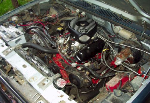
In addition to the fuel injection, I also rebuilt the engine at the same time, installed a mild performance camshaft and ported and polished the heads and intake. I also have an intake and EGR plenum from a mid-seventies mustang with a 2.8 liter. This intake has a slightly larger throttle bore, which lines up better with the TBI from the 3.8 liter, and makes the throttle body sit lower on the engine. It also has a large ‘vacuum’ port on the rear side which works well for the bypass valve. In addition to these, I have headers and a cold air intake setup.
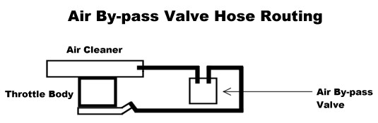
I fabricated an aluminum bracket for the air bypass valve and mounted it to the front of the TBI unit.
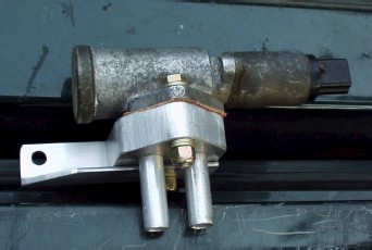
With the aluminum tube extending from the mount, I ran ½” rubber hose to the back of the EGR plenum and to the air intake after the filter. The diagram below shows this routing.
If you are attempting to keep the entire original smog equipment intake and functional, you will need to fabricate a few adapters.
The EGR valve from the 2.8 liter is not compatible with the 2.9 liter ECU. Also, the mount plates are different on both engines. So, you will need to fabricate an adapter from the 2.8 liter EGR mount to the 2.9 liter EGR valve. You will also need to run a high temperate line to the exhaust system at some point. I choose to use the air injection ports that tap the exhaust on the rear of the exhaust manifolds.
The electrical harness for the 2.9 liter has different connector plugs than the 3.8 liter TBI unit. This means that you will need to splice into the connectors for the throttle position sensor and the injectors. You will need to use the connectors from the 3.8 liter harness and splice them into the 2.9 liter harness.
The truck runs great, and DEFINITELY has more power. Before the rebuild and fuel injection conversion, I could never get the tires to even chirp, but now I can actually leave some rubber.
I hear the original carburetor in a 2.8L was rated at about 280 CFM, where as the CFI throttle body is closer to 350 CFM (From TRS posts). Larger exhaust will really help, and if time permits add a mild performance camshaft for increased power. The CFI also gives the 2.8 liter a nice idle sound.
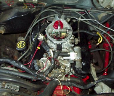
The following photo is with the K&N; air plenum installed. Yet to be added is a 4″ intake tube to a remote K&N; style filter. This tube will include two small ports for the air by-pass valve and the PCV tubing. I might include a heat shield to aid in cold air intake.
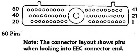
2.9 Liter EFI Wire to Pin Location and Color Codes
| Pin Number | Wire Color | Use |
| 1 | Yellow/Black | Keep-Alive Power |
| 2 | Light Green | Brake on-off (BOO) |
| 3 | Dark Green/White | Vehicle Speed Sensor (+) |
| 4 | Dark Green/Yellow | Ignition Diagnostic Monitor |
| 5 | Red/Light Green | Ignition Power (Switched) ???????????? |
| 6 | Black/White | Vehicle Speed Sensor (-) |
| 7 | Light Green/Yellow | Engine Coolant temperature Sensor |
| 8 | Orange/Light Blue | Fuel Pump Monitor |
| 9 | ———- | ———- |
| 10 | Tan/Yellow | A/C Compressor Clutch |
| 11 | ———- | ———- |
| 12 | ———- | ———- |
| 13 | ———- | ———- |
| 14 | ———- | ———- |
| 15 | ———- | ———- |
| 16 | Black/Orange | Ignition Ground |
| 17 | Tan/Red | Self Test Output and “Check Engine” |
| 18 | ———- | ———- |
| 19 | ———- | ———- |
| 20 | Black | Case Ground |
| 21 | Gray/White | Idle Speed Control (Bypass air) |
| 22 | Tan/Light Green | Fuel Pump |
| 23 | ———- | ———- |
| 24 | ———- | ———- |
| 25 | Light Green/Purple | Air Charge Temperature |
| 26 | Orange/White | Reference Voltage |
| 27 | ———- | ———- |
| 28 | ———- | ———- |
| 29 | Dark Green/Purple | Heated Exhaust Gas Oxygen Sensor |
| 30 | White/Black | Neutral Drive Switch (Automatic) |
| -OR- | White/Black | Neutral Gear/Clutch Engage Switch (Manual) |
| 31 | ———- | ———- |
| 32 | ———- | ———- |
| 33 | ———- | ———- |
| 34 | ———- | ———- |
| 35 | ———- | ———- |
| 36 | Yellow/Light Green | Spark Out, Timing Control (Spout) |
| 37 | Red | Vehicle Power |
| 38 | ———- | ———- |
| 39 | ———- | ———- |
| 40 | Black/Light Green | Power Ground |
| 41 | ———- | ———- |
| 42 | ———- | ———- |
| 43 | ———- | ———- |
| 44 | ———- | ———- |
| 45 | Dark Blue/Light Green | Manifold Absolute Pressure (MAP) |
| 46 | Black/White | Signal Return |
| 47 | Dark Green/Light Green | Throttle Position Sensor |
| 48 | White/Red | Self-Test Input |
| 49 | Orange | Heated Exhaust Gas Oxygen Sensor (-) |
| 50 | ———- | ———- |
| 51 | ———- | ———- |
| 52 | Tan/Light Blue | Shift Solenoid ¾ |
| 53 | ———- | ———- |
| 54 | Red | Wide-Open-Throttle A/C Cutoff |
| 55 | Tan/Yellow | A/C Compressor Clutch |
| 56 | Dark Blue | Profile Ignition Pickup (PIP) |
| 57 | Red | Vehicle Power |
| 58 | Light Green/White | Injector Bank 1 |
| 59 | Tan/Red | Injector Bank 2 |
| 60 | Black/Light Green | Power Ground |
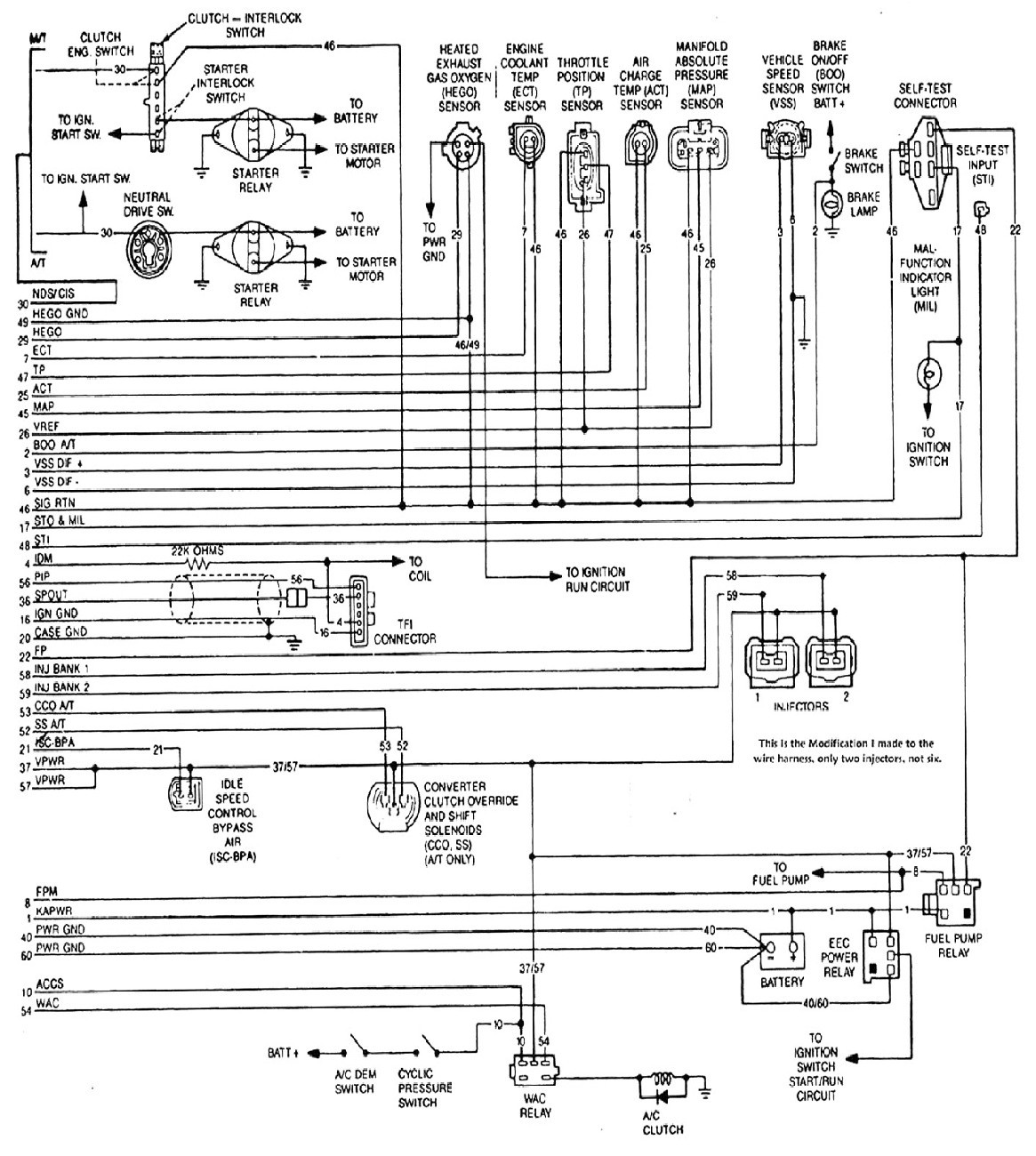
Wiring Diagram for Reference
1988-1990 Ranger/Bronco II 2.9L EEC-IV MAP, VIN code T
Resource: